JoyCon RCM Jig
Rationale
RCM mode is a diagnostic feature of the Switch that allows the device to execute unsigned code used for homebrew and CFW software. Entering RCM mode involves bridging (connecting) pin 10 on the joy con rail with a ground connection (found on pin 1, 7 and 9) while booting the device and holding Vol+. A typical RCM jig is a small piece of plastic which slides into the rail and aligns a short wire to connect the pins.
Instead of removing the joycon and using a separate jig each time RCM mode is required, we can short the rail pins from within the joycon controller while it’s still attached. By connecting the shorting circuit to an external button on the joycon, this can be done without removing the joycon at all. In this case, we use the joycon’s rail release button as it’s not wired into an existing circuit and avoids the need to modify the exterior of the controller.
Once completed, RCM mode can be entered by holding the Vol+ and rail release button during a reboot. The screen will remain black and the device will be available for injection.
Required
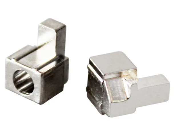
- Metal Joycon buckle lock
- See picture below
- Found on AliExpress or eBay
- The default plastic lock can be used with careful positioning of the wire.
- Stranded wire
- Sticky tape
- Soldering iron
- Screwdrivers – phillips head and Nintendo tri wing
Process
The first task is to open the right joycon controller and remove the rail mount. The instructions for this can be found on other sites (e.g. iFixit) and are not repeated here.
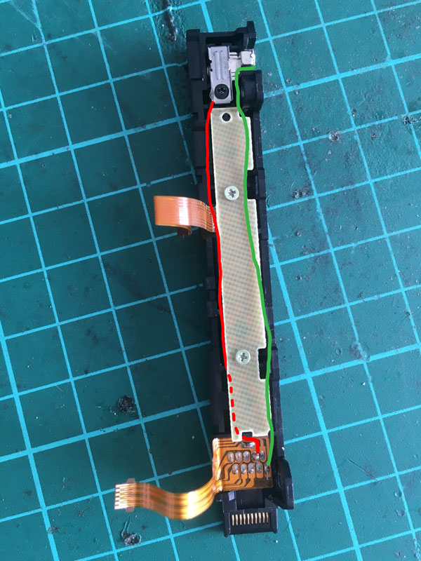
Once the rail is removed, the pin breakouts can be seen on the bottom of the rail. We need to connect two of these pins (7 and 10) to the physical button at the other end of the rail.
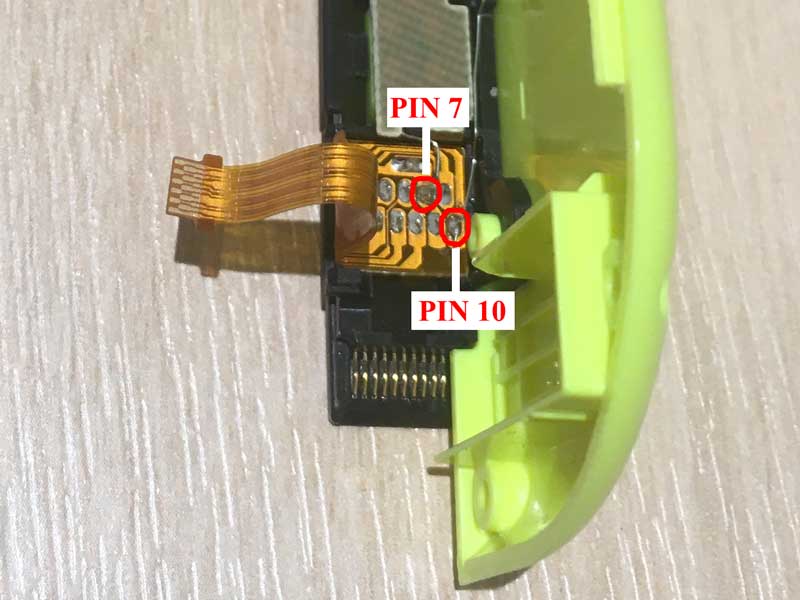
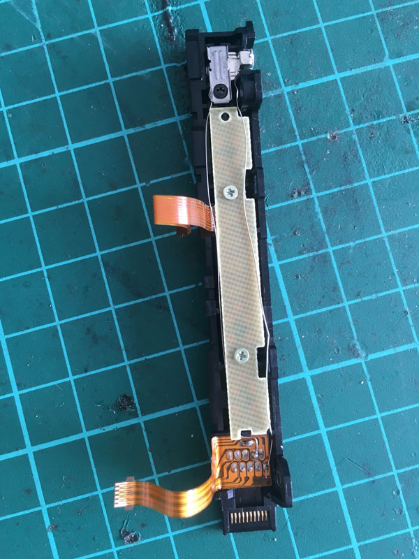
Two wires are soldered to the back sides of pins 7 and 10 and are run along the rail’s board. As the internals of the joycon case are tightly-fit, sheathed wires are difficult to find spare for. Therefore, a stranded wire is stripped and two strands used – care is taken to ensure that the paths used for these wires do not connect to other metal areas and create shorts. The wires are visible in the picture of the completed installation below and highlighted in the adjacent picture. Note the extra slack in the right (green) wire to allow for the travel distance of the button.
|
|
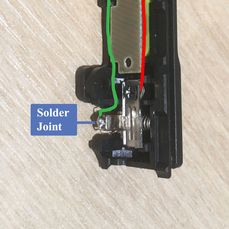
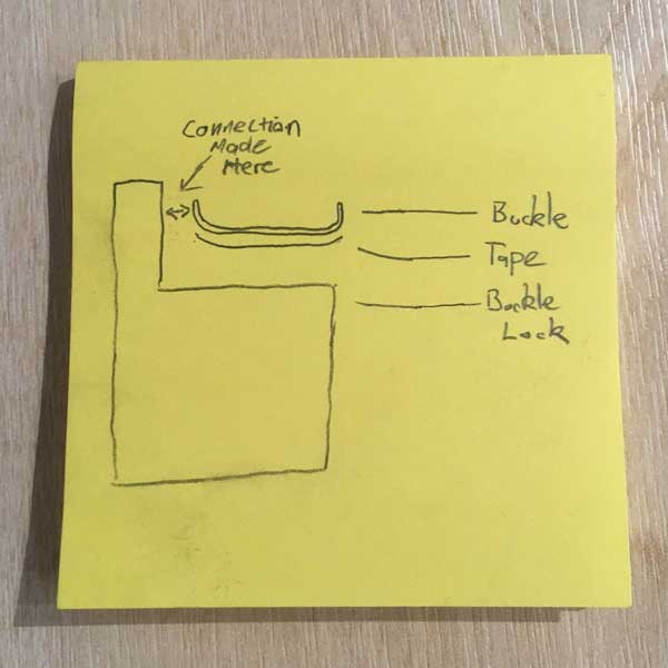
The plastic buckle lock is replaced with the metal buckle. At rest, the metal buckle does not touch the metal bracket above it, but as the button is pressed, a connection is made. Therefore the ends of the wires are connected to these components to make use of the button’s behaviour. The wire on the buckle lock is soldered to the ‘top’ of the piece (see the picture below). Make sure there is enough slack in the wire to allow for the required range of motion.
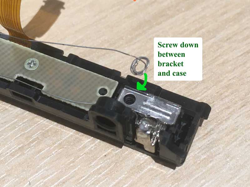
The other wire can be connected to the bracket piece without soldering – simply create a loop at the end of the wire for the screw to pass through and place it between the buckle and the plastic rail before replacing the screw.
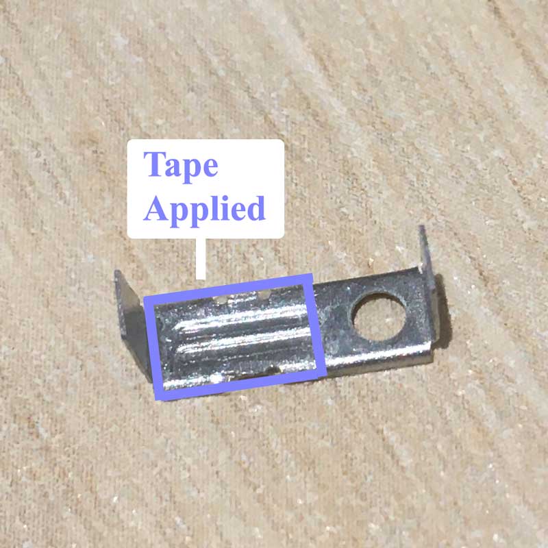
Before replacing the buckle over the wire loop, we add some circuit protection – because the rail is fixed rigidly to the switch but the joycons are sometimes flexed during play, the components inside the joycon sometimes apply pressure to the bracket and push it down onto the lock, completing the circuit. When using the Switch, this will manifest as the controller disconnecting until a few seconds after the pressure is released.
A small piece of sticky tape is applied underneath the bracket to prevent this electrical connection. The buckle therefore makes contact on the side of the bracket (i.e. only when pressed). The tape was applied so that it does not wrap around to cover the bracket edge used for this connection. There’s a small upward lip on the bracket used for the connection that must remain exposed – see the diagram.
 |
|
A multimeter can now be used to check that the connections are working correctly in both states – at rest and when the button is pressed.
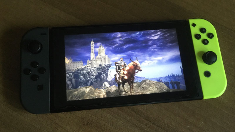
When restarting the Switch, holding the Vol+ and modified rail release buttons boots the Switch in RCM mode. When successful, the screen will not power on, but the RCM state can be verified by testing whether an injector detects the device. For example, connect the Switch to a computer via USB and try the injection on this site (must use Google Chrome). The Switch should appear as a device called APX. Note that some cheaper USB cables are used for charging and don’t transmit data, in which case they won’t work for this. If the device doesn’t appear, try a few different cables.
Note that jailbreaking the device requires additional steps to prepare an SD card, and are not covered here.
References
- This build is an extension of an idea from Discord user pbanj#9188 on the Nintendo Homebrew Discord Server
- A guide on jailbreaking the Switch can be found here.